| Model |
SG-4322 |
SG-4321 |
| Oscillation waveform |
Sine,Square,Pulse,Ramp,Parameter-variable(25 types),
Noise(Gaussian distribution),DC,Arbitrary |
| No. of channels |
2ch |
1ch |
| Insulation |
| ・ |
Each signal ground for CH1, CH2 and external 10MHz frequency reference input is independent. |
| ・ |
The signal grounds for waveform output, sync/sub output and external modulation/addition input are insulated from the housing.
(These signal grounds are common within the same channel.) |
| ・ |
The signal ground for external 10 MHz frequency reference input is insulated from the housing. |
|
| Output impedance |
50 unbalanced |
| Frequency |
Various modes |
| |
Mode |
Continuous, modulation,
and sweep (continuous/
single-shot) |
Sweep (gated Single-shot)and burst |
Sequence |
| Sine |
0.01μHz to 30MHz |
0.01μHz to 10MHz |
| Square |
0.01μHz to 15MHz |
0.01μHz to 10MHz |
| Pulse |
0.01μHz to 15MHz |
0.01μHz to 10MHz |
- |
| Ramp |
0.01μHz to 5MHz |
0.01μHz to 5MHz *2 |
Parameter-
variable |
0.01μHz tol 5MHz |
0.01μHz to 5MHz *2 |
| Noise |
The equivalent bandwidth is fixed to 26 MHz. |
| DC |
Frequency setting invalid |
| Arbitrary |
0.01μHz to 5MHz |
|
|
| Frequency accuracy*1 |
(3 ppm of setting + 2 pHz), aging rate*1: 1 ppm/year |
| Frequency setting resolution |
0.01μHz |
| Amplitude |
Setting range |
0 Vp-p to 20 Vp-p / open,
0 Vp-p to 10 Vp-p / 50Ω
AC + DC 10 V / open |
| Accuracy *1 |
(1% of amplitude setting [Vp-p] + 2 mVp-p) / open |
| Setting resolution |
999.9 mVp-p or less: 4-digit/0.1 mVp-p
1 Vp-p or greater: 5-digit/1 mVp-p |
| Setting unit |
Vp-p、Vpk、Vrms、dBV、dBm |
| Resolution of waveform amplitude |
Approx. 14 bits (36 mVp-p / open or greater) |
| Oscillation mode |
Continuous modulation, sweep, burst, sequence |
| DC offset |
Setting range |
10 V/open, 5 V/50Ω |
| Setting resolution |
499.9 mV or less: 4-digit / 0.1 mV, 0.5 V or greater: 5-digit / 1 mV |
| Accuracy *1 |
(│1% of DC offset setting [V]│+ 5 mV + 0.5% of
amplitude setting [Vp-p])/open (20C to 30C when
outputting sine waves of 10 MHz or less) |
Synchronous /
sub output |
Sync signals: TTL level
Internal modulation signal: - 3 V to + 3 V / open
Sweep X drive: 0 V to + 3 V / open |
| Sine wave |
Amplitude
frequency
characteristics *1 |
~100kHz :±0.1dB
100kHz ~ 5MHz :±0.15dB
5MHz ~20MHz :±0.3dB
20MHz ~ 30MHz :±0.5dB
(2.8Vp-p以上/ 50Ωでは±0.8dB)
(50mVp-p ~10Vp-p / 50Ω、1kHz基準) |
| Total harmonic distortion *1 |
10Hz ~20kHz : 0.2%以下(0.5Vp-p ~10Vp-p / 50Ω) |
| Harmonic spurious *1 |
| |
0.5Vp-p to
2Vp-p/50Ω |
2Vp-p to
10Vp-p/50Ω |
| to 1MHz |
- 60dBc or less |
- 60dBc or less |
| 1MHz to10MHz |
- 50dBc or less |
- 43dBc or less |
| 10MHz to 30MHz |
- 40dBc or less |
- 30dBc or less |
|
|
Non-harmonic
spurious *1 |
| to1MHz |
- 60dBc or less |
} |
|
| 1MHz to 10MHz |
- 50dBc or less |
( 0.5Vp-p to 10Vp-p / 50Ω) |
| 10MHz to 30MHz |
- 45dBc or less |
|
|
| Square wave |
Duty variable |
Normal: Setting range: 0.0100% to 99.9900%
Upper limit (%): 100 – frequency (kHz) /300
Lower limit (%): frequency (kHz) /300
Jitter: 300 ps rms or less typ.
Extended: Setting range: 0.0000% to 100.0000%
Jitter: 2.5 ns rms or less typ. |
| Rising/falling time *1 |
17ns or less |
| Overshoot |
5%or less typ. |
| Pulse wave |
Pulse width |
Duty setting range: 0.0170% to 99.9830%
Time setting range: 25.50 ns to 99.9830 Ms |
| Rising/falling time |
Setting range 15.0 ns to 58.8 Ms (3-digit/0.1 ns)
Rising/falling time independently set
The minimum setting value is 0.01% of period or 15 ns, whichever is larger. |
| Overshoot |
5%or less typ. |
| Jitter |
500 ps rms or less typ. (10 kHz or more)
2.5 ns rms or less typ. (less than 10 kHz) |
| Ramp wave |
Symmetry setting range: 0.00% to 100.00% |
Parameter-variable waveforms
(Can change the parameters specific to incorporated waveforms.) |
Can change the parameters specific to incorporated waveforms. |
Steady sine wave group |
Unbalanced sine, clipped sine, CF controlled sine, conduction
angle controlled sine, staircase sine, and multi-cycle sine waves |
| Transient sine wave group |
投On-phase controlled sine, off-phase controlled sine,
chattering-on sine, and chattering-off sine waves |
| Pulse waveform group |
Gaussian pulse, Lorentz pulse, Haversine, half-sine pulse, trapezoid pulse, and Sin (x)/x |
| Transient response waveform group |
Exponential rise, exponential fall, 2nd order LPF step response, and damped oscillation |
| Surge waveform group |
Oscillation surge and pulse surge |
| Others group |
Trapezoid with offset , half-sine edge pulse, and bottom referenced ramp waves |
| Arbitrary waveform |
Waveform length |
4 K to 512 K words (2n, n = 12 to 19) or the number of control
points is 2 to 10,000 (Control points are linearly interpolated.) |
Total of waveform
saving capaciy |
Up to 128 waves or 4 M words (total of channels 1 and 2),
saved in the nonvolatile memory. |
| Resolution |
16 bit |
| Sampling rate |
120 MS/s |
| Internal modulation |
Modulation waveforms |
Other than FSK and PSK: Sine, square (duty of 50%),
triangle (symmetry of 50%),
rising ramp, falling ramp, noise,
arbitrary waveforms
FSK and PSK: Square (duty of 50%) |
Modulation
frequency |
Other than FSK and PSK: 0.1 mHz to 100 kHz (5-digit/0.1 mHz)
FSK and PSK: 0.1 mHz to 1 MHz (5-digit/0.1 mHz) |
| External modulation |
Input voltage range |
1 V full scale (other than FSK and PSK) |
| Input impedance |
10 k, unbalanced (other than FSK and PSK) |
| Input frequency |
DC to 25 kHz (other than FSK and PSK)
DC to 1 MHz (FSK and PSK) |
| Modulation types and conditions |
FM |
Carrier waveform: Arbitrary waveform and standard waveform other than noise, pulse, and DC
Peak deviation: 0.00 Hz to less than 15 MHz |
| FSK |
Carrier waveform: Arbitrary waveform and standard waveform other than noise, pulse, and DC
Hop frequency: Within the frequency settable range for each carrier waveform |
| PM |
Carrier waveform: Arbitrary waveform and standard waveform other than noise and DC
Peak deviation : 0.000 to 180.000 |
| PSK |
Carrier waveform: Arbitrary waveform and standard waveform other than noise and DC
Deviation : –1800.000 to +1800.000 |
| AM |
Carrier waveform: Arbitrary waveform and standard waveform other than DC
Modulation depth: 0.0% to 100.0% (DSB-SC and non-DSB-SC supported) |
| DC offset modulation |
Carrier waveform: Standard waveform and arbitrary waveform
Peak deviation : 0 V to 10 V/open |
| PWM |
Carrier waveform: Square wave and pulse wave
Peak deviation : Square wave of normal duty variable
range : 0.0000% to 49.9900%,
Square wave of extended duty
variable range : 0.0000% to 50.0000%,
Pulse: 0.0000% to 49.9000% |
| Sweep |
Sweep types |
Frequency, phase, amplitude, DC offset, and duty |
| Sweep functions |
One-way (ramp wave shape)/shuttle (triangle wave shape) selectable
Linear/logarithmic selectable (only when sweeping the frequency) |
| Sweep range setting |
The start and stop values or the center and span values are specified. |
| Sweep time setting range |
0.1 ms to 10,000 s (4-digit/0.1 ms) |
| Sweep modes |
Continuous/single-shot/gated single-shot selectable Oscillation only occurs during sweep execution in the gated single-shot mode. |
| Trigger source |
Internal/external selectable |
| Internal trigger oscillator |
Period setting range: 100.0 s to 10,000 s (5-digit/0.1 s) |
| Stop level setting |
The signal level while oscillation is stopped in the gated single-shot sweep mode is specified.
Setting range: –100.00% to +100.00% (with reference to the full scale of amplitude) or off |
| Sweep input/output |
Sweep sync/marker output, sweep X drive output, sweep external control input, and sweep external trigger input |
| Burst/Trigger/Gate |
Burst modes |
Auto burst, trigger burst, gate, and triggered gate modes (The gate is turned on/off at each trigger in the triggered gate mode.) |
| Number of mark/space waves |
0.5 to 999,999.5 cycles, in 0.5-cycle units |
Number of oscillation
waves in the gate mode |
1 cycle/0.5 cycles selectable |
| Phase setting range |
–1800.000 to +1800.000 |
| Stop level |
The signal level while oscillation is stopped is specified.
Setting range: –100.00% to +100.00%
Oscillation stops at the set oscillation start/stop phase
when the stop level is set to off. |
| Trigger source |
Internal/external selectable, manual trigger allowed |
| Internal trigger oscillator |
1.0 s to 1,000 s (5-digit/0.1 s) |
| Trigger delay |
0.00 s to 100.00 s (5-digit/0.01 s)
Except for latent delay. Valid in the trigger burst mode only. |
| External trigger input |
TTL level, Input impedance 10 k (pulled up to +3.3 V), Unbalanced |
| Manual trigger |
Panel key operation |
| Sequence |
Step control parameters |
Step time, hold operation, jump destination, number of jumps, step stop phase, branch operation, step termination control, and step sync code output |
| Channel parameters in step |
Waveform, frequency, phase, amplitude, DC offset,
and square wave duty |
| Available waveforms |
• Sine, square, noise, DC, and arbitrary waveforms
• The ramp and parameter-variable waveforms can be
• used after being saved as arbitrary waveform. |
| Max. number of usable waveforms |
128 |
| Number of saved sequences |
10 sequences (saved in the nonvolatile memory) |
| Number of steps |
Up to 255 steps per sequence |
| Step time |
0.1 ms to 1,000 s (4-digit/0.01 ms) |
| Operation in step |
onstant, keep, and linear interpolation (except for waveform switching) |
| Number of jumps |
1 to 999 or unlimited |
| Branch operation |
ranched to the specified step when the branch signal is input. |
| 2-channel Ganged Operation (SG-4322 only) |
Channel modes |
Two channels independent, two phases (same frequency), constant frequency difference, constant
frequency ratio, and differential output (same frequency, amplitude, DC offset, reversed waveform) |
- |
| Equivalent setting, same operation |
Set two channels at the same time. |
Frequency difference
setting range |
0.00 Hz to less than 30 MHz (resolution: 0.01 Hz)
CH2 frequency – CH1 frequency |
Frequency ratio N:M
setting range |
1 to 9,999,999 (for N and M, respectively)
N:M = CH2 frequency:CH1 frequency |
| Phase synchronization |
Function to restart from the phase where the output waveforms for all the channels are set, automatic execution at channel mode switching |
| Other Functions |
External 10 MHz requency reference input |
Input voltage: 0.5 Vp-p to 5 Vp-p,
sine or square waves |
Frequency reference
output |
For synchronization when more than one SG-4322 and/or SG-4321 are used.
Output voltage: 1 Vp-p/50 , square wave, 10 MHz |
| External addition input |
Function |
Function to add the external signal to the waveform output signal |
| Addition gain |
×2/×10/off selectable
The maximum output voltage range is fixed to 4 Vp-p (×2) or 20 Vp-p (×10). |
| Input voltage/input frequency |
–1 V to +1 V
DC to 10 MHz (–3 dB) |
| Input impedance |
10kΩ, unbalanced |
| Multi input/output |
Used for sweep and sequence control |
Synchronization of
multiple units |
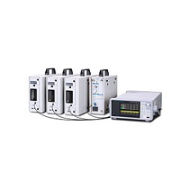
Sync operation is possible. Up to 6 units can be connected with BNC cables in the form of master / slave connections, using the frequency reference output and external 10 MHz frequency reference input. |
| User-defined unit |
Function |
Sets and displays the value in any unit, using a
specified conversion expression. |
| Setting target |
Frequency, period, amplitude, DC offset, phase, and duty |
| Conversion expression |
[(setting target value) + n] ×m or [log10 (setting target value) + n] ×m
The conversion expression, n and m are to be specified. |
| Unit character string |
Up to four characters |
| Memory to save setting |
10 settings can be memorized (saved in the nonvolatile memory). |
| Interface |
GPIB and USBTMC (SCPI-1999 and IEEE-488.2) |
| Display |
3.5” TFT color LCD |
| Power supply |
AC100 V to 230 V 10% (250 V max.) 50 Hz/60 Hz 2 Hz |
| Power consumption |
75VA max. |
50VA max. |
Operation temperature/
humidity range |
0C to +40C, 5%RH to 85%RH
(Absolute humidity: 1 g/m3 to 25 g/m3, no condensation) |
| Weight |
Approx. 2.1 kg (main unit excluding accessories) |
| Safety |
EN61010-1:2001 |
| EMC |
EN61326-1:2006 |
| Accessories |
・ Instruction Manual (Basic)
・ CD-ROM(PDF manuals, Arbitrary Waveform Editor
• Sequence Editor, LabVIEW driver)
・ Power cord set |